Concepts
Device adapters
Device adapters are implemented as AOP components and are running as special Extensions of the AOP Node.
Starting and exiting of Extensions is handled by WinGuard depending on the configuration. However, in principle it is also possible to install device adapters on remote computers and to manage and start them there independently.
A general AOP component becomes a Device adapter by providing the device adapter services and by using the corresponding Host Services. In addition, the component is of course free to implement and use any further API services.
For C++ and .NET component development comfortable SDKs are available that relieve the developer of a large part of the implementation details such as communication, object management and the basic component design. Basically, the development of a device adapter with the SDKs is therefore primarily limited to the definition of the object model and the implementation of the communication.
Objects
The device adapter does not map the connected IoT objects directly to WinGuard App Objects such as Datapoints, Events, etc., but provides them via a generic object model as an intermediate layer, with its members referred to as EXT Objects.
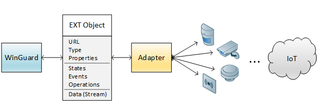
Usually such an EXT Object represents a real existing device, a component or a virtual functional unit with specific Properties, State, Events and Operations as well as data (e.g., video stream) if required. Using this model, it is in principle possible to describe all conceivable objects of the IoT in a unified way. For every type the Functionality is defined as XML definitions.
The URL uniquely identifies the EXT Object and additionally defines the object hierarchy, using ‘/’ as the separator token. In cases where the hierarchy is not recognizable from the addressing, the interface object contains an additional Path property not shown here, which then defines the hierarchy instead of the URL.
The task of the device adapter is merely the representation of the external real objects of the IoT into the defined object model and the execution of the described Operations on the objects. It is not concerned with internal processes and WinGuard App data objects.
For its own part, WinGuard independently maps the EXT Objects to the respective linked WinGuard App objects (e.g., Datapoints), evaluates States and Events and offers the execution of Operations.
Activities
In addition to the individual EXT Objects with their States and Events, processes in which several Objects are involved can also be identified, such as a telephone call, a camera display, a loudspeaker announcement or similar. We refer to these processes as Activities. Rather than being integrated into the EXT Objects themselves, these processes are represented by separate EXT Activities.
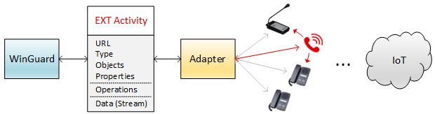
An EXT Activity contains all information, properties and states (both as properties) of a certain process, as well as a reference (via URLs) to the EXT Objects involved. EXT Activities are in many points similar to EXT Objects. An EXT Activity is also uniquely identified by an URL and has a type describing its Functionality. In addition, Operations can be executed on EXT Activities too, just like on EXT Objects.
In contrast to EXT Objects, EXT Activities are temporary objects with a start and an end, i.e., they come and go and are usually terminated by a user action (e.g., termination of a phone call).
An EXT Object is involved in an EXT Activity with a certain role, e.g., as a caller or a callee, as source or sink etc. Often an EXT Object can only participate in a certain EXT Activity with a specific role. This is predefined for the EXT Objects.
The fact that an EXT Object participates in an EXT Activity in a specific role represents an implicit State for this Object. Likewise there are often implicit Operations available for an EXT Object while it is involved in an EXT Activity and usually also operations in order to start such an Activity.
For Activities, a special UI is usually implemented in WinGuard. This means in particular that WinGuard depends on certain Activity types with fixed operations and properties in order to display and operate them in the UI. A device adapter should not define its own Activity types but use the predefined WinGuard Activity types. However, in principle it is possible to only support them to a limited extent and to implement additional properties and operations.
In a WinGuard network, Activities can be initiated on different stations, but will always be executed on the station where the Activity was created (i.e. only the device adapter instance that created the Activity will receive Activity Operations for it).
Types
Both objects as well as Activities have a type. For each type a unique functional Skill is defined in the XML definitions, e.g., which Properties, States, Events and operations are available, which Activities the object can be involved in, etc.
Similar to conventional programming languages, the type can best be considered as a class definition. For example types can also be defined by deriving them from other types and extending them, etc.
What makes it special is that the type is purely a logical class, as both EXT Objects and EXT Activities have the same generic data structure, regardless of their type.
Properties
Properties are fixed properties of an object. These include for example the addressing values as well as further static properties and information concerning the object if necessary. Any object-specific Settings are Properties too.
In WinGuard, Properties are transferred to the linked WinGuard object (usually a Datapoint) during the automatic data supply and can also be configured there. However, in contrast to the more dynamic States, values of Properties cannot be mapped to States or Events.
Important to understand: Both Properties and States are basically named values that are mapped as AOP Properties (→ AOP data model). In connection with EXT Objects, however, the term “Properties” refers to their logical meaning as fixed Properties.
Furthermore, an EXT Activity does not differentiate between Properties and States as the Activity itself is a dynamic object. It only has Properties that in this case can also be dynamic.
States and Events
States and Events are closely related. States are dynamic properties of an EXT Object, Events are dynamic events that occur or may occur for an EXT Object. In the API, they are not transmitted as part of the EXT Object but separately. They are also only transmitted from the device adapter to WinGuard but not vice versa. The primary task of an AOP device adapter is to keep States and Events of Objects in sync with the actual state of the connected third-party system.
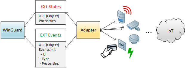
AOP knows two types of Events:
- Notification Events: These Events occur at a specific point in time. They have no lifetime and state.
- Examples: Access booking, license plate recognition
- Clearable Events: These Events occur for the duration of a certain time period, i.e., they are set and later cleared and have a start time and end time.
- Examples: Alarm, Fault
They also differ in the API that is used to transmit them to WinGuard (→ Extension Services). Clearable Events can sometimes be modeled alternatively as binary States.
Events can contain additional properties with information concerning the Event (such such as a person name or card number for an access booking).
Operations can target a specific Event instance rather than an Object (e.g., deferral of an alarm).
An Object may hold multiple (clearable) Event instances of the same Event type that are active at the same time.
Each Event instance is identified by an Event key which is an arbitrary case-sensitive string ID and unique for the respective Object.
Usually, this is a value received from the third-party system.
A URL may address an Event instance directly (i.e., to be used as an Operation target); the Event key is used as the address section following the Event type (e.g., ext[1]:Node[A]/Zone[2].event.Alarm[1234] where Alarm is the Event type and 1234 is the Event key).
If the third-party system does not allow multiple instances of the Event type, the Event type itself is used as Event key for the purpose of the adapter API.
In URLs, the address part may then be omitted (e.g., ext[1]:Node[A]/Zone[2].event.Alarm).
The Event key used to be called Event ID. Since the Module XML uses the id attribute to declare the Event’s Event type, this had caused misunderstandings. You may find that some old docs or SDKs still use the term Event ID to refer to the Event key.
A device adapter can freely define which States (e.g., “Open” = yes/no, “Temperature” = Value) and which Event types (e.g., “Alarm”, “Fault”, “UnauthorizedAccess”) an Object has. For each Event type, the possible Properties and Operations can be defined similar to the Object itself.
In the mapping, both States and Events can be mapped to App States in WinGuard, i.e., whether an alarm is modelled as a State or as an Event is not relevant for the representation in WinGuard. Similarly, both States and Events can be configured to trigger App Events or create system log entries in WinGuard.
Incidents
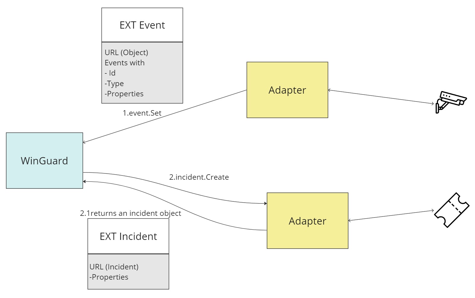
An Incident consists of a URL that uniquely identifies it and a set of arbitrary properties defined by an adapter which created it. It can, for example, represent a digital ticket from a ticketing adapter. WinGuard does not create or manage an Incident by itself but rather delegates these tasks to a device adapter. In return, the device adapter sends back an Incident object to WinGuard which can be attached to a WinGuard event. The figure below shows how an Incident is created using the properties and information of a WinGuard event.
Operations
Operations serve as a generic concept for control and operation of the connected Objects (and other entities) as well as for the flexible calling of specific Functionalities. Each Operation targets an adapter entity (EXT Objects, EXT Events, EXT Activities, or EXT Incidents) which is identified by its respective URL.
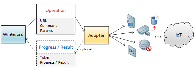
Each Operation can have a result (optionally, with additional Properties), or fail with an error.
In WinGuard, a series of so-called Functionalities are pre-defined in order to enable the execution of the same Operations across Objects and device adapters. With a Functionality, all Objects and Activities that support the same Functionality can be controlled uniformly. To do so, the adapter only has to declare to the Functionalities in the App XML and implement the corresponding Operations with identical parameters.
Apart from Operations defined by the Functionalities, WinGuard also provides other App Operations. These Operations are not integrated in Functionalities or Activities and can be set to Objects or to the Module itself.
Execution
We distinguish between two types of Operations with regard to their execution:
Operations with a direct result This is the standard case. The adapter directly returns the result or error.
Depending on the adapter, the feedback “successful” may mean that the command has fulfilled the desired purpose, but it can also mean that the Operation was only correctly transmitted and accepted for execution at the target and whether it actually succeeded is not known.
Long-running asynchronous Operations with optional progress reports The immediate return value contains only a token, indicating that the Operation has been transmitted correctly and started successfully. The token can then be used to send intermittent progress reports, and at last the final result of the Operation (return value or error).
Whether an Operation returns its result directly or is a long-running Operation is decided by the callee, i.e., the device adapter. The same applies to whether progress messages are transmitted during execution.
Note that the result must be provided in a timely manner, as a user may actively wait for the Operation’s result or at least some kind of observable progress. For Operations that typically take considerable time to finish (e.g., “ExportVideo”), Extensions should use long-running Operations and send regular progress updates.
⚠️ Operations that remain unanswered (i.e., no result/asynchronous Operation token/progress notification) for too long may get cancelled by the host application due to timeout. Also note that in this case, the host application may not be able to notify the Extension about the Operation being cancelled.
Resource return values
Some Operations (such as “ExportVideo” or “ExportImage”) may return large files as a result. By default, this data can be returned directly as a Property value of the Operation result. Alternatively, to avoid transmitting large files over the regular IPC connection, the Operation may also support transmitting the result data out-of-band as a resource. Refer to the respective Operation documentation to learn if the Operation supports this.
To implement out-of-band result transmission, the Operation must be long-running since a token is required.
After the immediate Operation result containing the token has been returned, use out-of-band resource transmission to send the resource.
The resource URL must be ext[<extension-code>]:operation[<operation-token>].
Finally, return the final Operation result containing a resource definition with the resource URL and transmission method put.
Functionalities
Just as types can be seen as analogous to classes in conventional programming languages, Functionalities can best be understood as interfaces.
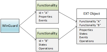
Functionalities are exclusively defined in WinGuard (→ WinGuard App). Each Functionality has a unique ID and - based on the definition of EXT Objects - optional properties, States, Events and Operations.
The mapping of an EXT Object specifies which Functionalities are supported by this object. In order to understand and operate objects comprehensively, WinGuard uses these Functionalities and can thus identify the corresponding objects.
For example there is the Functionality “ShowVideo”. Each object that supports this Functionality is offered for display in the VideoManager by WinGuard, regardless of whether it is actually an object of the type “Camera”. WinGuard understands the objects by their Functionality, so to speak.
What sets it apart is that an EXT Object does not necessarily have to implement the complete Skill of an assigned Functionality. The actually existing Properties, States, Events and Operations are always explicitly listed at the Object and only this Skill of Functionality is supported.
The assignment of a Functionality in principle only indicates for WinGuard a note to search for corresponding components of the Functionality in the object and to interpret them accordingly. As an option it can also be indicated that these are available at the Object under a different name.
The value types of Properties and States in the Functionality and the Object do not necessarily have to match, however they must be convertible into each other (→ AOP value types), otherwise the component is assumed as not existing.
Functionalities are thus a very broad form of interface in order to enable maximum flexibility. However, even if WinGuard tries to deal with that as best as possible, Functionalities should always be implemented entirely if possible.
Mapping
On the one hand the device adapter knows its EXT Objects with Properties, States, Events and Operations. On the other hand, WinGuard knows its Datapoints with domains, device types, Functionalities, States and Events. This logical connection is realized by the mapping.
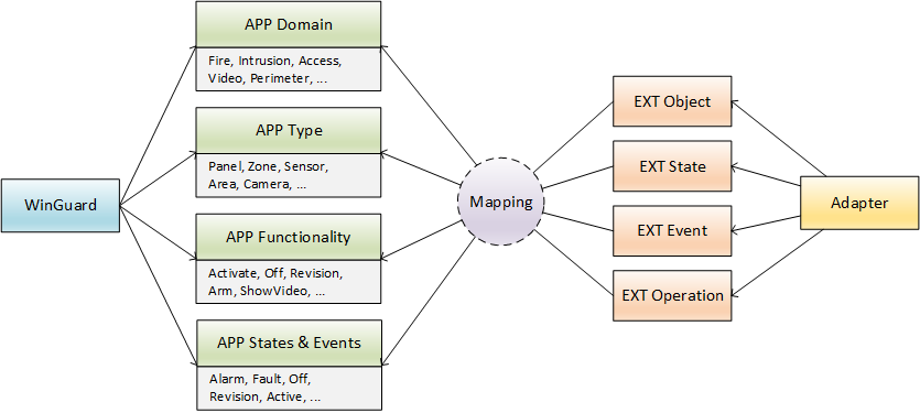
In order to define the mapping it is only required to insert an <App> section into the EXT Object definition. There, the app domain, its app device type, as well as optionally a number of app Functionalities are assigned to the objects. If required, a scheme for individual naming can also be defined there.
In addition, the EXT States and EXT Events of the object can be assigned to the WinGuard global App States, the triggering of App Events and logging. Further details are described in the section XML definitions.
The mapping is only interpreted by WinGuard and has no significance for the internal function of the device adapter.
Events can also have Functionalities, whereas only Properties and Operations can be part of the Functionality.
Node
A Node (often also called root) is a special object at the top level of the hierarchy. For the device adapter, it represents the “entry point” for addressing all objects subordinate to it. In most cases it represents a system. In case of a fire alarm system interface this is, e.g., the fire alarm system, in case of a CCTV interface these can be VCRs or in some cases the cameras themselves.
In many cases, such a Node is also the end point of a communication connection for the device adapter. For this purpose, it is usually defined in WinGuard for the device adapter and provided with all necessary information for establishing the connection. If the device adapter does not need an intrinsic address for its Node objects, they are identified by WinGuard via a free string ID. Otherwise, as usual, they are identified via the corresponding address property (e.g., for networked panels, the panel number on the bus).
The following graphic shows the connections and Nodes for five different device adapters schematically:
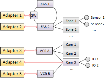
As can be seen, Nodes are not always also the end points of communication. In this example, adapter 1 will also realize FAS 1 and FAS 2 as Nodes - at least this would be the recommended practice. For the device adapters, these are logical Nodes, so to speak, that are connected via the gateway but behave like Nodes with regard to the addressing.
By convention, the first part of the URL of an EXT object is always the Node specification. Special device adapters that do not actually require a Node object (such as, e.g., Virtual) therefore use a pseudo Node (in this case “virtual”) to address the objects and are thus automatically also ready for any future Extensions.
Regarding the handling of Nodes, an adapter has the following alternative options:
Number of nodes
| Options | Description |
|---|---|
| Single Node | The device adapter can offer several Node objects for selection, however one of them must be explicitly selected. This is usually the case with device adapters that basically support several types of control panels but only one communication connection. In this case, the control panel to actually be connected has to be selected as the Node. If a second control panel is connected, another instance of the Device adapter has to be used. |
| Multiple Nodes | All Node objects provided by the device adapter can also be created simultaneously. Usually, such device adapters then also support several communication connections simultaneously. |
💡The marking is done in the XML Node section with the attribute multiple.
Number of connections
| Options | Description |
|---|---|
| Single connection | The connection data is usually specified in the device adapters Settings. |
| Multiple connections | The connection data is specified here in the Properties of the Node object. |
💡 The handling of the connections is done internally by the device adapter and is transparent for its users.
Available nodes determinable
| Options | Description |
|---|---|
| Nodes can be determined | In this case the Automatic Data Supply can be executed for the entire device adapter. Both the Nodes and their contained objects can be created. If the Node does not have a corresponding address property, the device adapter can set an arbitrary value as the address in the URL and does not need to provide an additional property that contains that arbitrary value. |
| Nodes cannot be determined | Node objects have to be created explicitly. Automatic data supply can only be executed for concrete Node objects. Special case: The device adapter supports only one fixed Node. In this case the automatic data supply can be executed for the device adapter and the handling of the Node is done implicitly. |
💡 The marking is done in the XML Node section with the attribute discoverable.
Object hierarchy
As can be seen from the graphic in the section Node, the EXT Objects of an device adapter are often hierarchically related to each other in terms of their addressing, with the Node at the top. We call that the object hierarchy of the interface. This is the physical hierarchy and not necessarily the logical hierarchy.

To address Sensor 1 here, for example, this is realized via adapter 2 → FAS 2 (= Node) → Zone 1 → Sensor 1. The URL described in the next section is structured accordingly, and the object hierarchy is directly visible and encoded within it. In cases where the URL does not contain a hierarchy definition, this is taken from the object’s optional path.
URL
The AOP URL is a concept used to address objects that is consistent throughout the AOP.
Each object of the application (internal or belonging to an extension) is uniquely identified by a URL.
Its basic AOP data type is string.
The structure of an AOP URL is defined as follows (augmented BNF as per RFC 2068):
; All string literals are case-insensitive.
AopUrl           =  [ StationOrigin ] [ ExtOrigin ] [ Path [ "." Tail ] ]

StationOrigin    =  "station" "[" Code "]" ":"
ExtOrigin        =  "ext" "[" Code "]" ":"

Path             =  PathSegment [ "/" Path ]
PathSegment      =  Name [ Address ]
Name             =  Symbol

Tail             =  PropertyOrState | ( "event." EventType [ EventKey ] )
PropertyOrState  =  Symbol
EventType        =  Symbol
EventKey         =  Address

Address          =  "[" 1*AddressChar "]"
AddressChar      =  <any character except "[" and "]"> | "[[" | "]]"
The URL may have a prefix which indicates the origin the addressed object belongs to.
Each origin prefix has a code and is terminated by a colon (:).
The station origin indicates a specific workstation; the ext origin indicates a specific extension.
A URL without any origin prefixes refers to a local application-internal (WinGuard-internal) object.
If the URL has both station and ext, station comes before ext.
The origin codes are defined as Codes.
The path of a URL is a sequence of path segments, separated by /.
Each path segment has a name and an optional address.
The first path segment is also called the root.
Path names are defined as Symbols. As such, types are case-insensitive, i.e., the upper/lower case is not distinguished.
In addresses, every character except [ ] can be used.
[ ] can be encoded into the URL by doubling, i.e., a [ is encoded as [[ a ] as ]] in the address specification.
Addresses are case-sensitive.
When comparing two AOP URLs for equality, all origin, path and tail segments have to appear in the same order.
Types/literals are compared case-insensitively and the addresses are compared case-sensitively.
For example, the URLs ext[1]:Panel[1] and EXT[1]:PANEL[1] are equal, but ext[1]:Panel[asdf] and ext[1]:Panel[ASDF] are not.
If GUIDs are used as addresses they should be rendered according to standard GUID text format rules, i.e., with braces and lowercase characters. Since address comparison is case-sensitive, this ensures that GUID addresses are compared correctly as well.
Here are some examples:
| URL | Description |
|---|---|
datapoint[{e83ad1ed-76e7-45b6-b1e8-90b114d11dac}] |
WinGuard datapoint with GUID E83AD1ED-76E7-45B6-B1E8-90B114D11DAC |
location[{0cb14f2d-d04e-4fb4-ae81-fa80ae5c35d4}] |
WinGuard location with GUID 0CB14F2D-D04E-4FB4-AE81-FA80AE5C35D4 |
ext[1]:FAS[1] |
EXT Object for FAS 1 of the Extension with Code 1 |
In particular with regard to the EXT Objects, the URL also defines the object hierarchy:
| URL | Description |
|---|---|
ext[2]:FAS[2] |
EXT Object for FAS 2 connected via Extension 2 |
ext[2]:FAS[2]/Zone[1] |
EXT Object for Zone 1 at the FAS 2 connected via Extension 2 |
ext[2]:FAS[2]/Zone[1]/Sensor[2] |
EXT Object for Sensor 2 of Zone 1 at FAS 2 connected via Extension 2 |
URLs of device adapter Objects always have the ext origin.
The URL path following the origin is derived from the definitions in the device adapter’s Module XML.
The first path segment refers to the Node; all following path segments address child Objects of this Node.
Each path name corresponds to the respective declared Object ID.
Each path segment may have an address: For Nodes if there may be multiple instances of this Node type (declared via multiple="1"); for other Object types if they declare an address property (address="1").
An AOP URL can not only address Objects but also Properties, States and Events of Objects.
The corresponding ID is appended to the URL of the Object, separated by a dot (.).
Since the IDs for Properties, States and Events of the same Object type may not overlap, the referenced Property/State is never ambiguous.
However, in order to clearly identify Events, they have the prefix event..
| URL | Description |
|---|---|
datapoint[{e83ad1ed-76e7-45b6-b1e8-90b114d11dac}].name |
Property “name” of the Datapoint with GUID E83AD1ED-76E7-45B6-B1E8-90B114D11DAC |
ext[1]:FAS[1]/Control[2].Active |
State “Active” of the EXT Object for Control 2 at the FAS 1 of the Extension 1 |
ext[1]:FAS[1].event.Alarm |
Event “Alarm” of the EXT Object for FAS 1 of the Extension 1 |
ext[1]:FAS[1].event.Alarm[123151] |
Event “Alarm” with unique Event key “123151” of the EXT Object for FAS 1 of the Extension 1 |
Special cases
Other device adapter entities, including Activities and Incidents, are also uniquely addressed by AOP URLs.
These URLs use reserved root names such as activity or incident.
For this reason, some root names must not be used as IDs for Node Objects as to not make these URLs ambiguous.
Refer to the Module XML documentation to learn which root names are reserved.
| URL | Description |
|---|---|
ext[2]:activity[showvideo1] |
Activity “showvideo1” belonging to Extension 2 |
ext[2]:incident[1234] |
Incident “1234” belonging to Extension 2 |
A URL may have both station and ext origins.
This is used for extensions that run at several workstations for redundancy or due to technical requirements (multistation trait).
In order to address an Object at a specific workstation, the URL is additionally prefixed by the station:
| URL | Description |
|---|---|
station[1]:ext[1]:FAS[1] |
FAS 1 of Extension 1 running at station 1 |
station[2]:ext[1]:FAS[1] |
FAS 1 of Extension 1 running at station 2 |
The extension itself, however, does not have to worry about that as the station prefix is used internally in WinGuard only.
All extension and device adapter APIs return/expect URLs that only have the ext origin.
Another special case is an AOP URL that only contains an origin. These URLs address the origin itself, rather than an object that belongs to that origin.
| URL | Description |
|---|---|
ext[1]: |
Extension 1 |
station[2]:ext[1]: |
The instance of Extension 1 running at station 2 |
The device adapter possesses one Object with URL ext[1]: which refers to the extension itself.
An empty string is a valid AOP URL and represents the case where a URL is “not set”. If a Property or parameter in the API is specified to be an AOP URL and an empty URL is a valid option for that specific instance, the specification should explicitly say so.
The concept of the URL quickly becomes clear by its use. In practice, a device adapter developer can simply use it as what it is intended to be, namely a unique ID for the EXT Objects and EXT Activities. Details of the implementation are handled by the SDKs.
Path
In some cases, Objects are not addressed with a hierarchical address specification as shown under URL, but, if necessary, independently of the classification in the hierarchy via a unique ID for each Object or similar, e.g.:
| URL |
|---|
| ext[1]:node[1]/object[1234-5678-aaaa] |
| ext[1]:node[1]/object[1234-5678-bbbb] |
In these cases, the object hierarchy cannot be determined from the URL. In such cases, EXT Objects can have the additional path field. This is then structured similarly with a ‘/’ syntax and then determines the physical object hierarchy instead of the URL. The path has no meaning beyond this.
Forms
A device adapter does not have an independent UI. However, individual user entries often have to be provided such as e.g., for editing the Settings, for entering parameters for automatic data supply, for defining specific protocol filters, etc.
For this purpose, the device adapter defines corresponding forms via XML structure in the XML definitions. These are used by WinGuard to enable user entries via a generic UI. The forms therefore can be said to define the UI, in a way.
Settings
It is possible to make Settings at various levels in a device adapter:
Configuration of the device adapter
These Settings are stored in the Config XML. They are used to make a device adapter configurable in order to be able to adapt function parameters even without changes to the source code. This may be necessary, for example, to react in practice to changes to the runtime environment such as external SDKs or similar. These Settings are all development-related and can only be made in the configuration file. The configuration Settings are available to the adapter even without connection to WinGuard.
Functional Settings for the entire device adapter
Functional Settings and their default values for the entire device adapter are defined in the Module XML. Here, a basic distinction is made between two types of Settings:
- Settings that are relevant for device adapters themselves, such as target addresses, timeout times, etc. and. For these Settings, a special form with the ID “Settings” can be defined, which is used for entries when Setting up the device adapter.
- Settings that are relevant for the use of the device adapter by WinGuard. The latter are already predefined by WinGuard for all device adapters, but you can adjust their default value by defining them in the Module XML. When Setting up the Extension instance for a device adapter, these Settings are automatically displayed in the form.
All Settings are stored in WinGuard and are only available to the device adapter via query after connecting to WinGuard. The definition of some Settings is required differently per coupling point (station). Such Settings are defined for profiles, which can then be assigned to one or more coupling points using WinGuard’s own means. For the device adapter itself, this process is transparent. When queried, the instance of the Device Adapter always receives the Settings currently valid for it.
For an object type
Settings for an object type are not possible at runtime, but only via editing the Module XML. They always apply globally for the object type and cannot be made different for coupling points.
For a specific object/node
These are Properties of the corresponding Object that can be entered when creating or editing the link. Upon Object definition, these Properties are stored in the same way and with the same attributes as for form definitions so that the user entries can be controlled accordingly. The entered values are stored at the linked WinGuard object.
Automatic data supply
Using automatic data supply, Datapoints and locations for EXT Objects can automatically be created and updated. The UI and most of the functionality for that are implemented centrally in WinGuard. However, the device adapter has to support the corresponding object query (“object.query”) as a service.
Parameters are partly required for the object query (such as e.g., path of the configuration files, passwords, addresses, filters, etc.). In order to enable that, the device adapter can define a corresponding form with the ID “DataSupply” which will be displayed on the first page upon data supply. The values entered there are transferred to the adapter upon object query.
If a file is defined in this form, the device adapter will receive both the path of the file as well as the content of the file. If, for example, a file with id “MyAPFile” is defined, the path will be transferred with id “MyAPFile” and the content will be transferred with id “MyAPFile@Data” as a base64 string.
In response to the object query, the device adapter returns the corresponding Objects according to the definition of its object model. Furthermore it can optionally define a property generation scheme for each object type separately in the Settings.
The device adapter can add special Properties to the returned Objects like @minval, @maxval and @path to enable a special hierarchical representation of the returned Objects and allow to preconfigure ranges for value objects.
Everything else such as the creation, updating or removal of the Datapoints is handled by WinGuard itself.
There are two types, discoverable and not discoverable Extensions.
- If the device adapter is discoverable, one or more Nodes (=root types) are automatically provided.
- If the device adapter is not discoverable, the Nodes need corresponding Datapoints. These Datapoints provide a custom configuration for the Node and must be manually created.
- Device adapters with a browsable Trait are considered as discoverable. Browsable Traits are deprecated, see table of Traits in Manifest XML.
- If a Node is browsable, then the device adapter is able to retrieve the Node’s children and their descendants.
- Both, discoverable device adapters and device adapters with browsable Nodes need to support the object browse (“object.browse”) function. The browse function requests the structure objects for a specific URL. The returned objects require only an id (URL) and a name. All other information about the EXT Object is not needed.
Property generation scheme
EXT Objects and the application objects they represent, such as Datapoints, are displayed in many places in the UI. This requires an identifier that is as easy to grasp as possible. However, the requirements for such an identifier often differ depending on the specific application case.
For the generation of the names, descriptions, and codes used, a scheme can be defined globally and individually for each object type. The following placeholders are available:
| Placeholder | Description | Used for Properties |
|---|---|---|
| ${node} | The root ID of the object type URL. | name, description, code |
| ${address} | The last address value part of the object type URL. | name, description, code |
| ${objecttype.code} | The object type of Extension link. | name, description, code |
| ${objecttype.code.last} | The last part of the object type (separated by a period) of the Extension link. | name, description, code |
| ${objecttype.name} | The name of the object type. | name, description |
| ${extension.code} | The Extension code. | name, description, code |
| ${extension.code.last} | The last part of the Extension code (separated by a period). | name, description, code |
| ${extension.name} | The Extension name. | name, description |
| ${devicetype.code} | The device type code. | name, description, code |
| ${devicetype.code.last} | The last part of the device type code (separated by a period). | name, description, code |
| ${devicetype.name} | The device type name. | name, description |
| ${devicetype.groupname} | The device type group name. | name, description |
| ${devicetype.groupcode} | The device type group code. | name, description, code |
| ${devicetype.groupcode.last} | The last part of the device type group code (separated by a period). | name, description, code |
| ${code} | The Datapoint code. | name, description |
| ${category.code} | The category code. | name, description, code |
| ${category.code.last} | The last part of the category code (separated by a period). | name, description, code |
| ${category.name} | The category name. | name, description |
| ${link.<prop>} | The desired Property. Instead <prop>, the respective property ID is used. | name, description, code |
If a specific object type has no pattern definition, the default pattern will be used, namely “${objecttype.name} ${address}” for name scheme and “${extension.code}.${objecttype.code}.${address}” for the code scheme.
The pattern for each object type can be defined in the Settings of the Extension or directly in step one of the Automatic data supply.
Logging
Extensions can use different logs:
Extension log
The extension log is used to log general behavior of the extension (e.g., launch/termination, connection establishment to third-party system, errors).
Extension log entries are transmitted from the extension to the AOP server via the AOP API, and are stored in WinGuard.
Some incidents (such as launch/termination of the extension process, effective State or Event changes) are logged automatically by the AOP server, sometimes depending on the configured log level.
Developers may add their own log entries.
Extension log entries are localizable.
IO log
The IO log captures the entire raw data traffic (binary or text-based, depending on the system) between the device adapter and the third-party system.
Like the extension log, entries are transmitted to the AOP server via the AOP API and stored in WinGuard.
The IO log is enabled separately, and is used to trace the behavior of the device adapter during commissioning or problem analysis.
SDK debug log
Extensions may also keep their own debug logs.
The AOP SDKs provided by Advancis store debug logs, typically found under C:\ProgramData\Advancis\debug\log.
It is used for low-level problem analysis and troubleshooting.
The SDK may use it to log internal program flow, warnings or errors.
It is possible for the extension to add their own log entries via methods provided by the SDKs, but it is recommended to use the Extension log instead for most concerns.
App logs (System log)
The system log stores system-wide incidents and user actions.
While it is not possible for an extension to add arbitrary entries to this log, it is possible to configure AOP to create system log entries based on certain State or Event changes in the device adapter.
This can be configured via App XML mapping definitions (<AppLog>).
Refer to the device adapter specification to learn for which domains and in which situations a device adapter should declare such mapping definitions.
The logging system is designed to meet the requirements of the standards VdS 3534 as well as DIN EN 50518.
Localization
Device adapters do not have their own UI and also do not need to translate any other strings. The strings that have to be translated are mostly contained in the XML file with the XML definitions. For each XML file there are related LNG language files that can be edited in an easy way with the Advancis Localizer. For example, if an XML file has the name “MyAdapter.xml”, the corresponding LNG files are named “MyAdapter_de.lng”, “MyAdapter_en.lng”, etc.
Even though the management of language resources and translation is realized directly in WinGuard and there is no need for the interface module developer to take any action, the functional principle is briefly explained below as this background knowledge can be helpful for designing the LNG files:
LNG files are basically simple CSV (Comma Separated Value) files that contain a list of assignments “<LNG ID>, String” for each language. An LNG ID itself is again only a simple string. However, in practice, it has proven useful to group the LNG IDs for more extensive language files by using dots in the name. Other strings can also be referenced from the contents using placeholders of the type “[<LNG ID>]”, as pictured in the following example with “[dict.name]”.
// WinGuard_de.lng
[dict.datapoint],"Datapoint"
[dict.name],"Name"
[state.alarm],"Alarm"
[query.entername],"Please indicate: [dict.name]"
WinGuard loads all required language files into its resource manager and merges the entries in a global list by adding the WinGuard-internal “mod:” namespace together with a context namespace to the respective source. The context namespace consists of the name of the device adapter. All strings can therefore reference each other across files by specifying the namespace, i.e., “[\mod:<ContextNamespace>:<LNG ID>]”. The global language resources do not have a namespace and can be referenced from other language files simply by prefixing the colon, i.e., “[:<LNG ID>]”.
// MyExt.de_lng
[Fire],"Fire"
[FireDatapoint],"[:dict.Datapoint]: [Fire]"
[state.alarm],"Fire alarm"
At last, a special user language file is loaded by WinGuard. The entries contained there offer the possibility to replace any entries of the other files.
// user_de lng
[dict.name],"Name"
[mod:MyExt:Fire],"Fire"
As a result, after loading the above three files, WinGuard would then have the following list of language resources and would translate on that basis.
// Global List
[dict.datapoint],"Datapoint"
[dict.name],"Name"
[state.alarm],"Alarm"
[query.entername],"Please indicate: [dict.name]"
[mod:MyExt:Fire],"Fire"
[mod:MyExt:FireDatapoint],"[:dict.Datapoint]: [Fire]"
[mod:MyExt:state.alarm],"Fire alarm"
The query of a language resource with an LNG ID is performed relative to a given local context. The resource management then first searches for the corresponding LNG ID in this context. If it is not found there, it searches in the context above, etc. Upon query of “[state.alarm]” you would receive the result “Fire alarm” in the context of “myadapter” and the result “alarm” in the global context.
To translate the entries in the XML files, WinGuard automatically searches for specific LNG IDs. For example, the name of an Object with the ID “MyObject” is searched in the language resources with the LNG ID “obj.myobject”, an Operation with the ID “Off” as LNG ID “operation.off”, etc. See also XML definitions.
Resources
Events and Operations may have additional resources (e.g., cardholder image in Events, audio or video file in Operations). Events and Operations provide definitions of these resources, containing the type of the resource, the method the resource is provided and additional Properties. Operations may also return resources.
A resource is either requested from the adapter (get) or pushed to WinGuard (put).
The adapter also has to request the Operation resources from WinGuard.
Small resources may be transferred directly in the IPC call or response, large resources (greater than 1 MB) should be transferred over the more efficient out-of-band HTTP data transfer (OOB). The decision whether to transfer the resource via IPC or OOB is always made by the sender.
Resource out-of-band HTTP transmission
Out-of-band HTTP transmission only works for put resources.
To transmit a resource out-of-band, send an HTTP PUT request to http(s)://<aop-host>:<aop-port>/resource/<resource-url>.
aop-host and aop-port are the hostname/IP and port of the AOP server, respectively.
resource-url is the URL-encoded resource URL.
You must send the HTTP header session containing your session ID to associate the HTTP request to your IPC connection.